

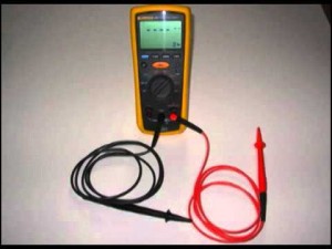
Fluke 1507 Insulation Tester How To Use
Fluke 1507 insulation resistance tester is a great examination tool which makes maintenance test more thorough and troubleshooting more effective. Before performing measurements using this tester, information technology is recommended to get throughFluke 150x serial insulation resistance testerintroduction to enhance more than knowledge regarding this tester.
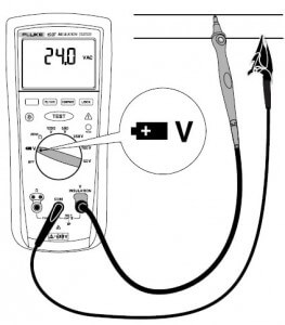
How to measure voltage using Fluke 1507 insulation resistance tester?
Steps for measuring voltage are:
- Insert the test probes into V insulation and COM terminals.
- Turn the rotary switch to 5/
 labelled function.
 - Select the voltage ranges from 0.1V to 600V equally per your need.
- Brusque the ends of the probe by connecting it to the battery for Dc voltage or to any switch for Ac voltage.
- By connecting the probes, the output voltage should get-go appear on the display of the tester.
- Note the measurement brandish on the screen. When you lot have noted the readings, remove the probes safely to avoid any electric shock or impairment to the device.
- Set upward for measurement of AC & DC voltage are shown below in the figure.
How to measure Globe bond resistance using Fluke 1507 insulation resistance tester?
E'er perform resistance tests on de-energised circuits because information technology will adversely effect the device under test.
Steps for measuring Globe bond resistance are:
- Insert examination probes in the Ω and COM input terminals.
- Turn the rotary switch to the Zero Ω labelled function.
- Press the bluish coloured push subsequently shorting the ends of the probes together and look until dashes appear on the display.
- The insulation tester at present starts measuring the probe resistance, stores the reading in retentiveness and subtracts it from the terminal readings.
- You tin can relieve the probe resistance reading even when the Tester is turned off but if the probe resistance is greater than 2Ω, the resistance will not be saved.
- Connect the probes to the excursion to be measured. The tester automatically detects if the excursion is energised or non by because these weather condition:
- The brandish shows —- until y'all printing the Test labelled push and a valid resistance reading is obtained.
- If the voltage is greater than 2V then the master display warns past showing the high voltage symbol. In this condition, the test is inhibited and it is recommended to disconnect the tester and remove the power before proceeding.
- When you lot press the Test labelled button if the tester chirps indicate that the test is inhibited because the voltage is present at the probes.
- To start the test press and hold the TEST labelled push. The Exam labelled icon appears on the lower portion of the display until you release the Examination labelled push button.
- The resistance reading starts appear on the screen and remains on the display until new the test is started.
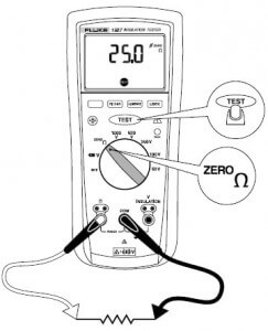
Notation: When resistance is higher than the maximum display range, the Tester displays the > symbol and the maximum resistance for the range.
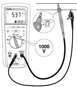
How to mensurate Insulation resistance using Fluke 1507 insulation resistance tester?
Steps for measuring insulation resistance are:
- Insert test probes in the Ω and the COM input terminals.
- Turn the rotary switch to the desired test voltage.
- Connect the probes to the circuit to be measured. The tester automatically detects if the excursion is energised or not by considering these atmospheric condition:
- The display shows —- until you press the Test labelled button and a valid resistance reading is obtained.
- If the voltage is greater than 30V then the primary display warns by showing the loftier voltage symbol. In this status, the test is inhibited and information technology is recommended to disconnect the tester and remove the power earlier proceeding.
- When y'all press the TEST labelled button, if the tester chirps indicate that the exam is inhibited because the voltage is present at the probes.
- To commencement the test, press and agree the TEST labelled push. The secondary brandish shows the test voltage applied to the excursion under test. Sponsored Links
- The loftier voltage symbol forth with a primary display shows the resistance in the MΩ or GΩ. Until TEST labelled push button is released the examination proper name icon will appear on the lower portion of the brandish.
- Proceed the probe on the test points and release the Examination labelled button. The excursion under test and then discharges through the tester.
What is polarization Index and Dielectric assimilation ratio and how to measure it with Fluke 1507 insulation resistance tester?
Polarization Index is the ratio of the 10-infinitesimal insulation resistance to the 1-minute insulation resistance while Dielectric Absorption Ratio (DAR) is the ratio of the i-minute insulation resistance to the 30-second insulation.
Insulation tests should merely be performed on de-energised circuits. At present for its measurement we take to follow these steps given below:
- Insert exam probes in the Ω and the COM input terminals.
- Turn the rotary switch to the desired examination voltage.
- To select polarisation Index or dielectric absorption ratio, printing the PI/DAR labelled button.
- Connect the probes to the circuit to be measured. The tester automatically detects if the circuit is energised or not by considering these atmospheric condition:
- The display shows —- until you press the Test labelled button and a valid resistance reading is obtained.
- If the voltage is greater than 30V then the primary display warns by showing the loftier voltage symbol. In this condition, the exam is inhibited and information technology is recommended to disconnect the tester and remove the power before proceeding.
- When you lot press the TEST labelled push, if the tester chirps indicate that the examination is inhibited because the voltage is present at the probes.
- To start the test, press and concur the Test labelled button. The secondary display shows the test voltage applied to the circuit nether examination.
- The loftier voltage symbol along with a chief display shows the resistance in the MΩ or GΩ. Until Examination labelled button is released the test proper noun icon will announced on the lower portion of the display.
- When the test is completed, the PI or DAR value is displayed on the principal display.
Hope you all similar this commodity.For whatsoever suggestions or query please comment below.We always capeesh your suggestions.

Fluke 1507 Insulation Tester How To Use,
Source: https://analyseameter.com/2015/09/measurements-fluke-1507-insulationtester.html
Posted by: beckdiden1961.blogspot.com
0 Response to "Fluke 1507 Insulation Tester How To Use"
Post a Comment